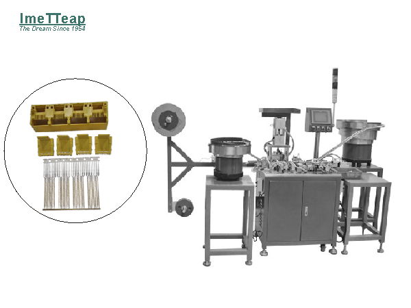
GENERAL INTRODUCTION
This Automated 4P RJ Connector Assembly Machine provides the posibility to allow the RJ connector manufacturers to achieve an full automatic assembly solution
from component parts loading, feeding, processing, assembly, inspection, Testing, sorting, seperating & final unloading.
By this one-stop assembly automation solution, manufacturers of RJ connector can reduce their manpower investment in production line and also can improve
product quality as well as production rate as they expected.
ASSEMBLY FLOW
Terminal Pin Loading & Feeding
Due to flexible features of terminal pin in strip, coil feeding method is the most popular loading and feeding solution for this kind of raw materials.
Generally, there are various of terminal pin in differetn shapes from flat terminal pins to round terminal pins;
Coil Feeder can achieve an automatic loading and feeding for blanking material, stamping parts or semi-finished product and to transfer component parts to
processing, assembling, testing, sorting work station.
It will be prior to manual loading and feeding that requires small quantity, large-size or complex components;
The working principle of coil feeder consists of support tension mechanism, straightening device and cutting mechanism.
Mostly, the straightening & cutting mechanism often are mounted on the assembly machines.
The strength of this coil feeding system as below:
High Precise feeding performance to guarantee the parts/components feeding speed and location to next station;
Excellent Performance to be used in continuous processing or assembly production flow;
Flexible Feeding speed to comply with assembly machine assembly production rate and assembly production cycle time;
Simple mechanism, economic investment, low breakdown rate as well as easy-to-maintenance;
Plastic Core Loading & Feeding
Vibatory Feeder bowl is selected here for loading and feeding the plastic core.
Vibratory feeder bowl is the most versatile of all feeding devicees fro small engineering or machining parts. Vibratory feeder bowl can be introduced to load small
size metal stamping parts, small size plastic molding parts. Feeder Tracks long which the parts travel is helical and passes around the inside wall o a shallow
cylindrical bowl. The bowl is usually supported on three or four sets o inclined leaf springs secured to a heavy base.
Vibratory is applied to the bowl bottom from an electromagnet mounted on the base, and the support system constrains the movement o the bowl so that it has a
torsional vibration about its vertical axis, coupled with a linear veritcal vibration. The motion is such that any small portion of the inclined track vibrates along a
short, approximated straight path, which is inclined to the horizontal at an angle greater than that o the track. When component parts are placed in the bowl, the
effect of the vibratory moiton is to cause them to climb up the track to the outlet at the top of the bowl. Before considering the characteristics of vibratory-bowl
feeders, it is necessary to examine the mechanics of vibratory conveying. For this purpose, it is convenient to deal with the motion of a part on a straight vibrating
track that is inclined at a small angle to the horizontal.
Parts Orientating Mechanism
To build an automatic full-custom assembly machine, the parts must be correctly oriented when they are fed to the workstation. The mechanism employed to
ensure this fall into two groups: those that are incorporated in the parts feeder, which are usually referred to as in-bowl tooling, and those that are fitted to the
chute between the feeder and the workstation, called out of bowl tooling. The devices used for in-bowl tooling very often work on the principle of orienting by
rejection and may be termed passive orienting devices. Withi this type of device, only those parts that, by chance, are fed correctly oriented pass through the
device, while the other parts fall back into the hopper or bowl. The rejected parts are then refed and make further attempts to pass through the orienting device.
In some cases, devices are fitted that can reorient parts. These may be termed active orienting devices and, although they are not widely applicable, they have the
advantage that no reduction in feed rate occurs as a result of the rejection of parts. In some cases, orienting devices are fitted between the parts feeder and the
automatic workstation; With this system, rejected parts cannot easily be returned to the parts feeder, and orienting devices employed in this way are usually of the
active type.
Terminal Cutting, Insertion and Bending
Terminal Pin from coil feeder is designed to feed to the work station one by one. Then the cuttting mechanism will cut the terminal pins in set or independently,
then a clamping system will clamp and hold the terminal pins, then after align with the plastic core ports, perform an automatic pushing and insertion movement
to insert the pins into the ports of plastic core. Pin terminal after inserted into plastic core will be bending in accordance with product design concept.